【物联网无线通信技术】LoRa从理论到实现(SX1268)
511人参与 • 2024-08-02 • 物联网
文章目录
lora技术前序
lora之前的主要无线通信协议分为一下三种:
- 第一类是远距离高速率的传输协议,典型协议包括蜂窝网络通信技术,如3g、4g、5g相关技术等,这是我们目前移动通信使用的典型技术。
- 第二类是近距离高速率传输技术,如wifi、蓝牙等,这些技术传输距离在几十到几百米级别,主要用在家庭环境和日常应用中,使用非常广泛,前面两类可能是一般用户最常使用到的网络协议了,也符合传统网络应用的主要特点和需求。
- 第三类是近距离低功耗传输技术,如传统物联网中zigbee、rfid、低功耗蓝牙等。
上面三类技术大都要求较高的信噪比,并且对障碍的穿透性较小,无法在复杂环境中实现远距离低功耗传输。低功耗广域网有效的弥补了现有物联网连接方法的不足,成为支持物联网连接的重要基础,得到了国内外的广泛关注,并成为了国内外的研究和应用前沿。
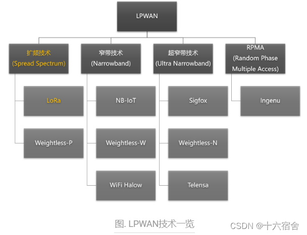
lpwan (low power wide area network)指的是低功耗广域网,其特点在于极低功耗,长距离以及海量连接,适用于物联网万物互联的场景。lpwan不只是一种技术,而是代表了一族有着各种形式的低功耗广域网技术,如下图所示。其中lora使用的是一种扩频技术,nb-iot使用的是窄带技术,这是两种有代表性的低功耗广域网技术。
lora技术简介
lora 是 long range communication的简称,我们可以从三个不同的角度来理解lora这门技术。从而获得对lora这么技术完整的理解。
- lora本质上指的是一种物理层的信号调制方式,是 semtech 公司定义的一种基于chirp扩频技术的物理层调制方式,可达到-148 dbm的接收灵敏度,以偏小的数据速率(0.3-50kbps)换取更高的通讯距离(市内3km,郊区15km)和低功耗(电池供电在特定条件下可以工作长达10年)。
- 从系统角度看,lora也指由终端节点、网关、网络服务器、应用服务器所组成的一种网络系统架构:lora定义了不同设备在系统中的分工与作用,规定了数据在系统中流动与汇聚的方式。
- 从应用角度看,lora为物联网应用提供了一种低成本、低功耗、远距离的数据传输服务:lora在使用10mw射频输出功率的情况下,可以提供超过25km视线传输距离,从而支持大量广域低功耗物联网应用。
lora应用
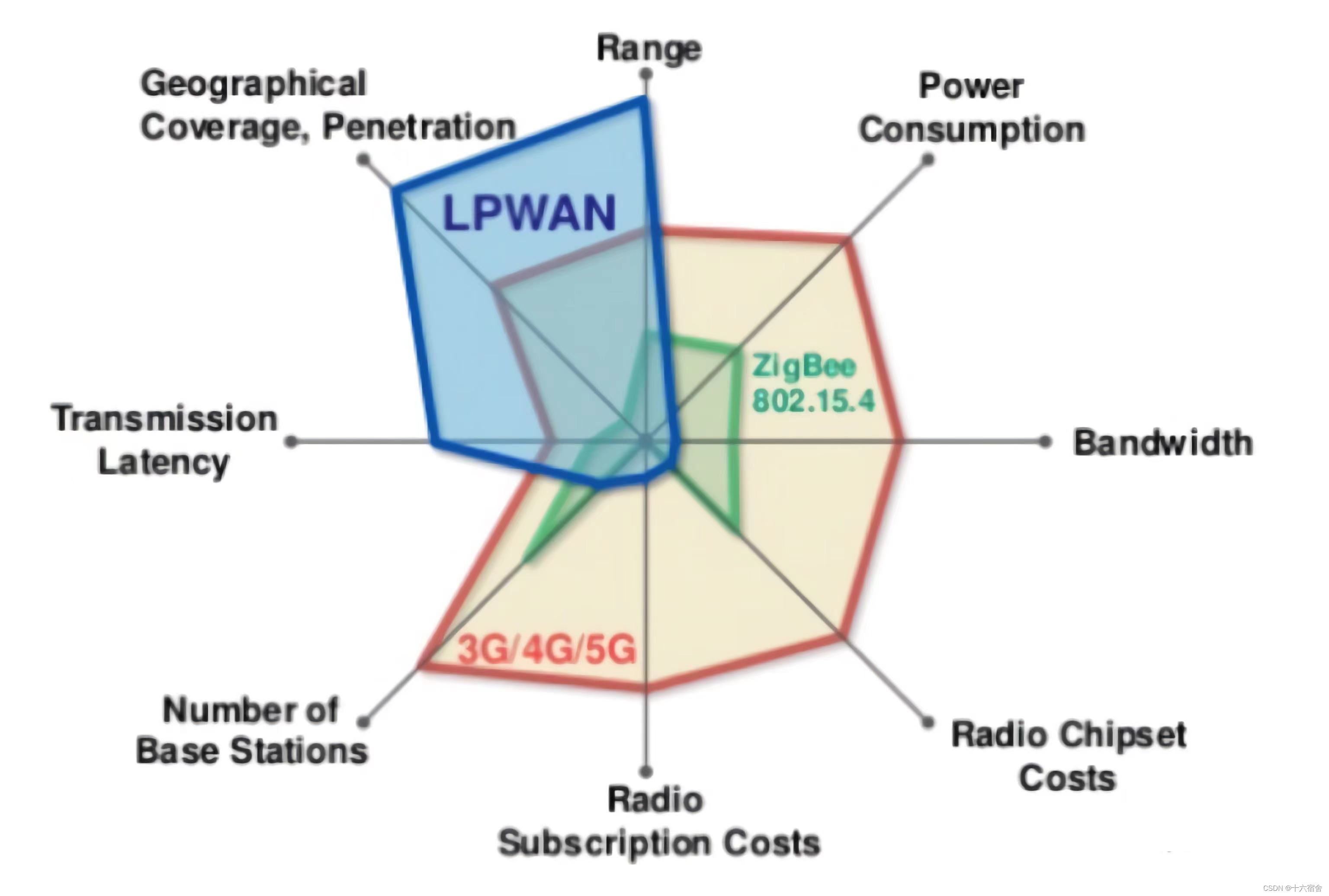
lora作为目前广泛使用的低功耗广域网技术(lpwan),为低功耗物联网设备提供了可靠的连接方案。 如下图所示,相比于wi-fi、蓝牙、zigbee等传统无线局域网,lora可以实现更远距离的通信,有效扩展了网络的覆盖范围; 而相比于移动蜂窝网络,lora具有更低的硬件部署成本和更长的节点使用寿命,单个lora节点可以在电池供电的情况下连续工作数年。 lora具有低数据率、远距离和低功耗的性质,因此非常适合与室外的传感器及其他物联网设备进行通信或数据交互。
考虑到lora在覆盖距离、部署成本等方面的巨大优势,近年来lora在全球范围内进行了大量的应用部署,在智能仪表(如智能水表、智能电表)、智慧城市、智能交通数据采集、野生动物监控等众多物联网场景中都可以看到lora的应用。例如lora通信模块与传统的水质传感器进行连接,从而使用户可以数十公里外远程监控饮用水在输送过程中的水质变化情况。而在荷兰的kpn项目中,工程人员通过广泛部署lora网关,实现lora网络全覆盖,为智慧运输、智能农业、智慧路灯等具体应用提供了通信支持。
lora系统架构
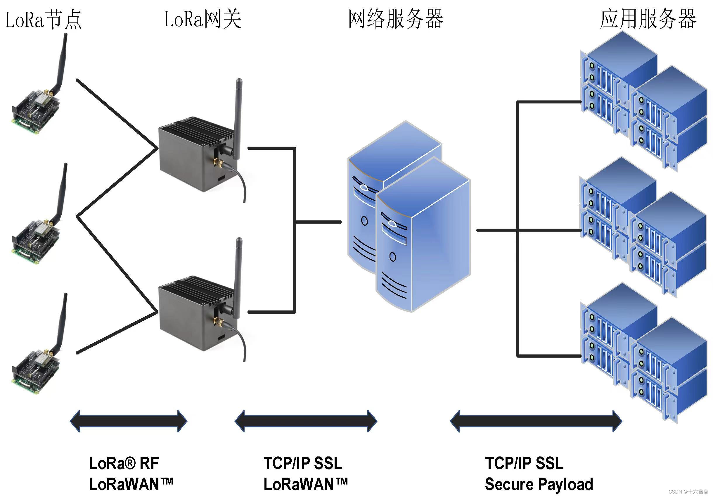
现在常用的lora架构由节点、网关及服务器所组成,各部分的关系如下图所示。 lora节点与网关之间采用单跳直接连接,这一阶段的物理层使用线性扩频调制(chirp spreading spectrum, css),mac层(media access control,媒体访问控制)通常使用lorawan协议。
网关收到数据包后,对数据包信号进行解码,并将解码结果通过蜂窝或有线网络传输给网络服务器,这一阶段使用传统的tcp/ip进行传输,同时网络服务器与网关之间的交互仍然遵守lorawan协议。 网络服务器汇总多个网关的数据,过滤重复的数据包,执行安全检查,并根据内容将数据发送至不同的应用服务器,供用户读取和使用,这一阶段也使用tcp/ip和ssl进行传输和加密。
lorawan
在lora网络中,会有很多lora节点向同一网关发送数据,这就需要mac协议来协调不同节点间的数据传输,在lora中比较典型的mac协议就是开源的lorawan。 lorawan是由lora联盟在lora物理层编码技术的基础上提出的mac层协议,由lora联盟负责维护。lorawan规范1.0版本于2015年6月发布。lorawan协议主要规定了节点与网关、网关与服务器之间的连接规范,确定了lora网络的星型拓扑结构。受lora节点成本和能耗的限制,现有的lorawan协议基本采用纯aloha机制,即节点在发送数据前不进行载波侦听,也就是没有使用csma/ca,而是随机选择时间进行发送。
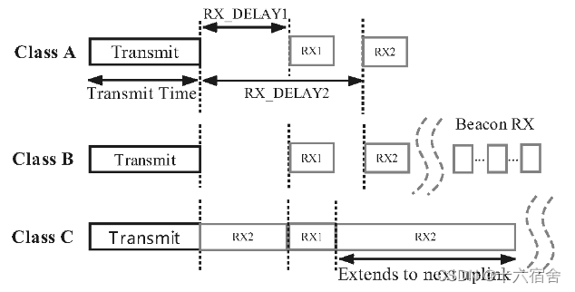
lorawan定义了网络的通信协议和系统架构,还负责管理所有设备的通信频率,数据速率和功率。 在lorawan的控制下,网络中的所有设备可以是异步的,并在只有可用数据时进行传输。 针对不同的应用场景,lorawan定义了三种节点运行模式,分别是class a(all)、class b(beacon)、class c(continuously listening):
- class a模式主要提供低功耗上行连接,处于class a模式的节点可以在任意时间发起上行传输,并只在传输结束时打开两个下行接收窗口,此时接收来自网关ack。class a模式下,网关无法主动连接到节点,当无数据传输时,节点处于休眠状态,因此该模式下节点能耗最低。
- class b模式提供节点与网关的周期性连接,该模式下网关节点周期性向节点广播信标帧,保持节点与网关的时间同步。
- class c模式提供节点与网关的持续性连接,该模式下节点始终处于唤醒状态,因此能耗最高。
三种网络模式中,class a是所有lora网络都必须支持的模式,也是最常用的网络模式。这三个模式设计并不复杂,其实就是在网络灵活性、可用性和节能之间的一个平衡。class a最节能,但是灵活性相对较低,例如下行数据只能依赖于上行数据的时间。class c最耗电,但是也是上行和下行数据发送最灵活的。
lora通信物理层
我们来介绍lora通信的基本原理,包括调制、解调、编码和解码,着重于物理层协议的分析,关于上层协议(如lorawan),有很多其他的资料和开源实现供读者学习[1][2],这里就不详述了。
需要说明的是,lora物理层是一个商用的私有协议,并没有完整公开的协议说明,因而已有的一些lora实现[3][4][5][6][7]都是依照semtech公司的相关专利和文件猜出来的。[6]matlab版本用于原型验证和离线操作,[7]基于gnuradio平台的c++版本则是一个实时的高性能lora实现。很多对lora的说法只是基于大家的观察和理解,同时很多lora代码实现的性能是很差的,包括不少研究论文中使用的lora代码,实际性能也存在着很大的问题。
相关论文的介绍见[8]: zhenqiang xu, pengjin xie, jiliang wang. "pyramid: real-time lora collision decoding withpeak tracking", ieee infocom 2021. [pdf]
lora调制与解调
在这节我们介绍lora的调制与解调,也即如何在物理波形和比特数据之间进行转换。
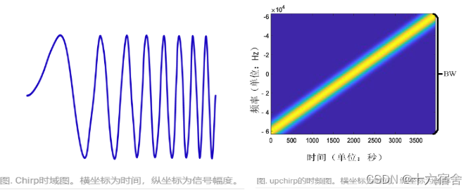
lora 使用 css (chirp spread spectrum)线性扩频调制,频率线性扫过整个带宽,因此抗干扰极强,对多径和多普勒效应的抵抗也很强。lora的基本通信单元是linear chirp,也即频率随时间线性增加(或减小)的信号。我们将频率随着时间线性增加的chirp符号叫做upchirp,将频率随着时间线性减小的chirp符号叫做downchirp。如下图分别从时域波形和时频域展示了一个upchirp的图像:
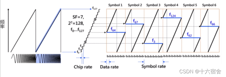
一个chirp怎么编码数据呢?lora的做法是通过在频域循环平移chirp进行数据的编码,不同的起始频率代表不同的数据。如下图所示,在带宽b内四等分标定四个起始频率,我们可以得到4种类型的符号,分别表示00,01,10,11。所以在接收端,只需要将这个起始频率计算出来,就可以计算出每一个chirp对应的比特数据。我们将下图(a)所示从最低频率扫频到最高频率的chirp符号称为basic upchirp。
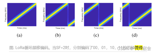
lora规定了一个参数sf(spreading factor,扩频因子),如上图所示,在带宽一定的情况下,扩频因子的增加意味着采样时长的增加(扫频速度减低)。可以看出,提高sf,虽然在相同时间减少了可以传输的实际数据,但是这样扩频后传输可以降低误码率,灵敏度越高,可以得到更远的传输距离。
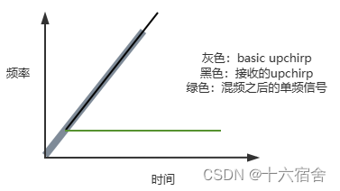
lora解调过程,实质就是求出chirp符号的起始频率,其做法通常是这样的:首先将收到的基带upchirp信号与downchirp点乘,化为单频信号,这一操作叫做dechirp(解扩频)。这个过程可以简单理解为两个收到的upchirp信号与basic upchirp进行混频,就可以得到upchirp的启始频率。如下图所示。
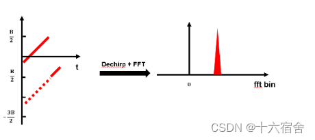
dechirp之后,对得到的信号进一步做fft(快速傅里叶变换),即可在频域获得一个峰值,这个峰值位置对应的频率即是接收到upchirp的起始频率,我们因此得到对应sf个比特的数据。如下图所示。
一个完整的lora数据包结构包含三个部分:前导码(preamble)、sfd(start frame delimiter)和数据部分(data)。 前导码包含6~65535个basic upchirp和两个标识网络号的其他chirp符号。接着是2.25个basic downchirp,作为sfd标识数据段的开始。后面的数据段则包含着若干编码了数据的data chirp。
当我们使用软件无线电设备(software-defined radio, sdr)接收一段lora设备发出的信号,并用inspectrum这个软件(其他可画时频图的软件或代码也可以)把信号的时频图画出来,那么它大概会是如下样子:

lora 编码与解码
lora物理层编码过程如下:
- 包头共2.5个有效bytes,包尾循环纠错编码。
- hamming 编码
- interleaving将每字节的位转化到物理层对应的多chirp频率(8 bits/byte => sf bits/symbol),从下图可以看到实际的口空发射与数据之间的关系。
- gray 解码(gray code => binary code)
lora采用循环纠错编码(crc)进行前向错误检测与纠错,但会产生传输开销。编码率越大前向纠错越强,链路抗干扰性越强,但是传输开销将会加大,进而加大传输时间。
lora物理层解码过程与编码相反,如下:
- 格雷码编码(gray coding)
- 对角交织(interleaving)
- 海明解码(hamming decoding)
- 包头解析(header decoding)与crc(校验crc checksum)
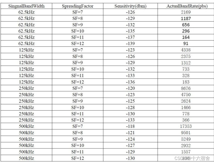
补充说明一下:在仅仅增加带宽的情况下,能有效的提高传输速率。下图是带宽与sf对接收数据dbm底线以及传输速率的对应数据。
stm32+sx1268实现lora
实现原理
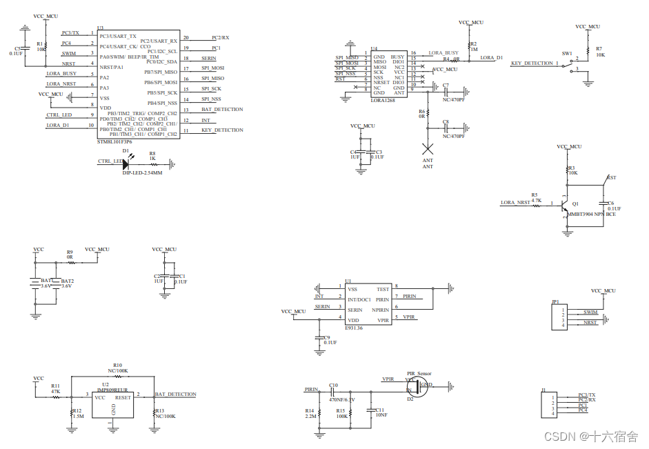
mcu选择stm81l101f3p6s实现超低功耗,其与lora射频芯片sx1268之间采用spi通信接口。
嵌入式程序
下面的嵌入式程序为main函数,主要实现了三个部分功能的调用实现。
- sx126x芯片初始化。
- 将lora接收的数据通过串口打印的功能。
- 通过摁键触发lora发送数据。
oid main(void)
{
    u8 extidelay = 0;
    u8 txbuffer[5] = {0x11,0x22,0x33,0x44,0x99};

	clk_masterprescalerconfig(clk_masterprescaler_hsidiv1);	//1分频,16mhz

    //串口初始化
    usart1_init();

    //sx126x初始化
	sx1276m_gpioint();
	cs_low;
	delayxms(5);
	cs_high;
	reset_high;
	reset_sx1262();//reset rf
	sx1262_config();//频率431.5m
	rx_init();//接收模式

    //按键初始化
	gpio_init(gpiob, gpio_pin_1, gpio_mode_in_fl_no_it);//pb1按键

  	while(1)
  	{
    	if(gpio_readinputdatabit(gpiob, gpio_pin_1))
    	{
            extidelay++;
            delayxms(1);
            if(extidelay > 10)
            {//消抖
            	extidelay = 0;
            	if(gpio_readinputdatabit(gpiob, gpio_pin_1))
            	{
    				keytrigger_flag = 0;
    				lora_txdata(txbuffer, 5);//lora发送数据
    				delayxms(30);//等待一会再接收,发射和接收不能同时进行
        			sx1262_config();
        			rx_init();//切回接收模式
            	}
            }
    	}
        hal_sx1268_rxhandle();//等待接收
	}
}

void usart1_init(void)
{
	gpio_init(gpioc, gpio_pin_3, gpio_mode_out_pp_high_fast);
	gpio_init(gpioc, gpio_pin_2, gpio_mode_in_pu_no_it);
	clk_peripheralclockconfig(clk_peripheral_usart,enable);//使能串口外设时钟
	usart_init(115200,                      //波特率115200
			   usart_wordlength_8d,         //数据位8
               usart_stopbits_1,            //停止位1
			   usart_parity_no,             //无奇偶校验
			   usart_mode_tx|usart_mode_rx);//usart初始化
	usart_itconfig(usart_it_rxne,enable);//使能接收中断
	usart_cmd(enable);//使能usart
	//usart1_sendstr("usart_tx is ok");
}

void hal_sx1268_rxhandle(void)
{
  	if(irq_databit)//wait for the irq rxdone or timeout
	{
		irq_status = getirqstatus();//0x02
		if((irq_status&0x02) == rxdone_irq)
		{
			getrxbufferstatus(&packet_size, &buf_offset);	//read rx packet_size
			if(packet_size>0)
			{//接收长度大于0
				readbuffer(buf_offset, &rxbuf[0], packet_size); 	//read rx data

				usart1_sendstring(&rxbuf[0], packet_size);//串口打印接收数据
				clearirqstatus(rxdone_irq);//清除中断
			}
			else
			{
				clearirqstatus(rxdone_irq);
			}
			rx_init();
		}
	}
}
下面是sx1628芯片的驱动代码,包括初始化,发送模式接收配置,数据发送等具体的接口实现。
/*
 * the following firmware is provided: (1) "as is" with no warranty; and
 * (2)to enable access to coding information to guide and facilitate customer.
 * consequently, semtech shall not be held liable for any direct, indirect or
 * consequential damages with respect to any claims arising from the content
 * of such firmware and/or the use made by customers of the coding information
 * contained herein in connection with their products.
 *
 * copyright (c) semtech s.a.
 */

#include "stm8l10x.h"
#include "sx1268-lora.h"
#include "string.h"

void sx1276m_gpioint();

u8 gb_sf;
u8  gb_bw;
u8  cr;	//lr_regmodemconfig1

#define crc   0x01  //crc enable

#define data_len        (13)

/**********************************************************
**parameter table define
**********************************************************/
//__root const u16 sx1276freqtbl[3] = {0x066c, 0x0780, 0x0800}; //434mhz
__root const u16 sx1276freqtbl[3] = {0x06d9, 0x0700, 0x0800}; //868mhz @ 26m


__root const u16 sx1276powertbl[4] =

{
  0x09ff,                   //20dbm
  0x09fc,                   //17dbm
  0x09f9,                   //14dbm
  0x09f6,                   //11dbm
};


__root const u8 sx1276lorabwtbl[10] =
{// 0        1     2       3      4       5         6      7       8      9
//7.8khz,10.4khz,15.6khz,20.8khz,31.2khz,41.7khz,62.5khz,125khz,250khz,500khz
  0,1,2,3,4,5,6,7,8,9
};

__root const u8 sx1276spreadfactortbl[7] =
{
  6,7,8,9,10,11,12
};


u8  sx1276data[11];

u8  gb_rxdata[256];                                         //receive data buffer

#if 1  //sx1268  aloma
#define payload_length    13
#define payload_length1    11

#if 0
u8  txbuf[payload_length] = {'s','e','n','d','_','t','e','s','t'};
#else
u8  txbuf[payload_length];
#endif
u8  txbuf_1[payload_length1] = {'r','e','t','u','r','n','_','t','e','s','t'};
u8 rxbuf[200];

u8 packet_size;
u8 buf_offset;


u8 irq_status;
u8 tx_buff_flag;
extern u16 lux_data;
extern u8 stm8s_id[12];
extern u8 frameid;
#endif

void delayms(unsigned int t)
{
	unsigned int i;
	unsigned char j;
	for(i=0;i<t;i++)
	for(j=0;j<120;j++);
}

void delayxms(unsigned int t)//8m内部晶振下,已测试
{
	unsigned int i;
	unsigned int j;
	for(i=0;i<t;i++)
	//for(j=0;j<1600;j++);//8m主频
	for(j=0;j<3200;j++);//16m主频
}

void sx1276m_gpioint()
{
    //***** rf_sck         pc_odr_odr4
    gpio_init(sck_port,sck_pin , gpio_mode_out_pp_low_slow);
    //*****rf_miso       pc_idr_idr5 //input
    gpio_init(miso_port,miso_pin , gpio_mode_in_pu_no_it);//上拉输入
    //*****rf_mosi       pc_odr_odr6
    gpio_init(mosi_port,mosi_pin , gpio_mode_out_pp_low_slow);
    //*****rf_nsel_pin
    gpio_init(cs_port,cs_pin , gpio_mode_out_pp_low_slow);
    rf swt
    //busy
    gpio_init(busy_port,busy_pin , gpio_mode_in_pu_no_it);
    //irq
    gpio_init(lora_rcv_irq_port,lora_rcv_irq_pin, gpio_mode_in_fl_no_it);
    //reset
    gpio_init(reset_port,reset_pin , gpio_mode_out_pp_low_slow);
}

#if 1//aloma  sx1268
u8 spi_rw(u8 data)
{
	u8 i;

	for (i = 0; i < 8; i++)//高位先传
	{
		if (data & 0x80)
			mosi_high;
		else
			mosi_low;

		data <<= 1;
		sck_high;
 		if (miso_databit)//高位先收
			data |= 0x01;
		else
			data &= 0xfe;

		sck_low;
	}
	mosi_low;
	return (data);
}

/***************sx1262*****************/
void reset_sx1262(void)
{
	reset_low;
	delayxms(1);		//more thena 100us, delay 10ms
	reset_high;
	delayxms(1);	//delay 10ms
}

void check_busy(void)//发送时,busy拉低
{
	unsigned char busy_timecnt = 0;
	while(busy_databit)
	{
		delayxms(1);
		busy_timecnt++;
		if(busy_timecnt>5)		//超时120ms复位
		{
			busy_timecnt=0;
			//setstandby(0);		//0:stdby_rc; 1:stdby_xosc
			reset_sx1262();		//reset rf
			//sx1262_config();
			//rx_init();
			break;
		}
	}
}

void setsleep(void)
{
	u8 opcode,sleepconfig;

	check_busy();
	opcode = set_sleep;	//0x84
	sleepconfig = 0x00;	//bit2: 1:warm start; bit0: 0: rtc timeout disable

	cs_low;
	spi_rw(opcode);
	spi_rw(sleepconfig);
	cs_high;
}

//0:stdby_rc; 1:stdby_xosc
void setstandby(u8 stdbyconfig)
{
	u8 opcode;

	check_busy();
	opcode = set_standby;	//0x80

	cs_low;
	spi_rw(opcode);
	spi_rw(stdbyconfig);
	cs_high;
}

void settx(u32 timeout)
{
	u8 opcode;
	u8 time_out[3];

	check_busy();
	opcode = set_tx;	//0x83
	time_out[0] = (timeout>>16)&0xff;//msb
	time_out[1] = (timeout>>8)&0xff;
	time_out[2] = timeout&0xff;//lsb

	cs_low;
	spi_rw(opcode);
	spi_rw(time_out[0]);
	spi_rw(time_out[1]);
	spi_rw(time_out[2]);
	cs_high;
}

void setrx(u32 timeout)
{
	u8 opcode;
	u8 time_out[3];

	check_busy();

	opcode = set_rx;	//0x82
	time_out[0] = (timeout>>16)&0xff;//msb
	time_out[1] = (timeout>>8)&0xff;
	time_out[2] = timeout&0xff;//lsb

	cs_low;
	spi_rw(opcode);
	spi_rw(time_out[0]);
	spi_rw(time_out[1]);
	spi_rw(time_out[2]);
	cs_high;
}

//0:gfsk; 1:lora
void setpackettype(u8 packettype)
{
	u8 opcode;

	check_busy();
	opcode = set_packet_type;	//0x8a

	cs_low;
	spi_rw(opcode);
	spi_rw(packettype);
	cs_high;
}

u8 getpackettype(void)
{
	u8 opcode;
	u8 status;
	u8 packettype;

	check_busy();
	opcode = 0x11;

	cs_low;
	spi_rw(opcode);
	status = spi_rw(0xff);
	packettype = spi_rw(0xff);
	cs_high;

	return packettype;
}

//rf_freq = freq_value * 32m / (2^25)  ----->  freq_value = (rf_freq * (2^25)) / 32m
//431.5m : freq_value = (431.5m * (2^25)) / 32m = 452460544 = 0x1af80000
//868m : freq_value = (868m * (2^25)) / 32m = 910163968 = 0x36400000
void setrffrequency(void)
{
	u8 opcode;
	u8 rf_freq[4];
	u32 rffreq = 0;

	//rffreq = 0x1b200096;//434m
	rffreq = 0x1af80000;//431.5m : freq_value = (431.5m * (2^25)) / 32m = 452460544 = 0x1af80000
	check_busy();

	opcode = set_rf_frequency;	//0x86

	rf_freq[0] = (rffreq>>24)&0xff;//msb
	rf_freq[1] = (rffreq>>16)&0xff;
	rf_freq[2] = (rffreq>>8)&0xff;
	rf_freq[3] = rffreq&0xff;//lsb

	cs_low;
	spi_rw(opcode);
	spi_rw(rf_freq[0]);
	spi_rw(rf_freq[1]);
	spi_rw(rf_freq[2]);
	spi_rw(rf_freq[3]);
	cs_high;
}

void setpaconfig(void)
{
	u8 opcode;

	check_busy();
	opcode = 0x95;

	cs_low;
	spi_rw(opcode);
	spi_rw(0x04);	//padutycycle//22dbm
	spi_rw(0x07);	//hpmax:0x00~0x07; 7:22dbm
	spi_rw(0x00);	//devicesel: 0: sx1262; 1: sx1261
	spi_rw(0x01);
	cs_high;
}

void setregulatormode(void)
{
	u8 opcode;

	check_busy();
	opcode = 0x96;

	cs_low;
	spi_rw(opcode);
	spi_rw(0x01);//regmodeparam
	cs_high;
}

void writeregister(u16 address, u8 *data, u8 length)
{
	u8 opcode;
	u8 addr_l,addr_h;
	u8 i;

	if(length<1)
		return;

	check_busy();
	addr_h = address>>8;
	addr_l = address&0xff;

	opcode = 0x0d;
	cs_low;
	spi_rw(opcode);
	spi_rw(addr_h);//msb
	spi_rw(addr_l);//lsb
	for(i=0;i<length;i++)
	{
		spi_rw(data[i]);
	}
	cs_high;
}

void readregister(u16 address, u8 *data, u8 length)
{
	u8 opcode;
	u8 addr_l,addr_h;
	u8 i;

	if(length<1)
		return;
	check_busy();

	addr_l = address&0xff;
	addr_h = address>>8;

	opcode = 0x1d;
	cs_low;
	spi_rw(opcode);
	spi_rw(addr_h);//msb
	spi_rw(addr_l);//lsb
	spi_rw(0x00);	//20190809 fix
	for(i=0;i<length;i++)
	{
		data[i]=spi_rw(0xff);
	}
	cs_high;
}

/*
@para
power:
-17(0xef) to +14(0x0e) dbm by step of 1 db if low power pa is selected
-9(0xf7) to +22(0x16) dbm by step of 1 db if high power pa is selected

ramptime:
-------------------------------------
ramptime 	  | value | ramptime(μs)
-------------------------------------
set_ramp_10u    0x00    10
set_ramp_20u    0x01    20
set_ramp_40u 	0x02	40
set_ramp_80u 	0x03	80
set_ramp_200u 	0x04	200
set_ramp_800u 	0x05	800
set_ramp_1700u 	0x06	1700
set_ramp_3400u 	0x07	3400
*/

void settxparams(int power,u8 ramptime)
{
	u8 opcode;
	u8 data_buf[2];

	// workaround - better resistance of the sx1262 tx to antenna mismatch, see ds_sx1261-2_v1.2 datasheet chapter 15.2
    // regtxclampconfig = @address 0x08d8
	readregister(0x08d8,data_buf,1);
	data_buf[0] = data_buf[0]|(0x0f << 1);
        writeregister(0x08d8,data_buf,1);
    // workaround end

	check_busy();
	opcode = set_tx_params;	//0x8e

	cs_low;
	spi_rw(opcode);
	spi_rw(power);
	spi_rw(ramptime);
	cs_high;
}


void setbufferbaseaddress(u8 tx_base_addr,u8 rx_base_addr)
{
	u8 opcode;

	check_busy();
	opcode = set_buf_base_addr;	//0x8f

	cs_low;
	spi_rw(opcode);
	spi_rw(tx_base_addr);
	spi_rw(rx_base_addr);
	cs_high;
}

void writebuffer(u8 offset, u8 *data, u8 length)
{
	u8 opcode;
	u8 i;

	if(length<1)
		return;

	check_busy();
	opcode = 0x0e;
	cs_low;
	spi_rw(opcode);
	spi_rw(offset);
	for(i=0;i<length;i++)
	{
		spi_rw(data[i]);
	}
	cs_high;
}


void readbuffer(u8 offset, u8 *data, u8 length)
{
	u8 opcode;
	u8 i;

	if(length<1)
	return;
	check_busy();

	opcode = 0x1e;
	cs_low;
	spi_rw(opcode);
	spi_rw(offset);
	spi_rw(0xff);
	for(i=0;i<length;i++)
	{
		data[i]=spi_rw(0xff);
	}
	cs_high;
}

void getrxbufferstatus(u8 *payload_len, u8 *buf_pointer)
{
	u8 opcode;
	u8 status;

	check_busy();

	opcode = 0x13;
	cs_low;
	spi_rw(opcode);

	status = spi_rw(0xff);
	*payload_len = spi_rw(0xff);
	*buf_pointer = spi_rw(0xff);
	cs_high;
}

void setmodulationparams(u8 sf, u8 bw, u8 cr, u8 ldro)
{
	u8 opcode;

	check_busy();
	opcode = 0x8b;

	cs_low;
	spi_rw(opcode);

	spi_rw(sf);//sf=5~12
	spi_rw(bw);//bw
	spi_rw(cr);//cr
	spi_rw(ldro);//ldro lowdatarateoptimize 0:off; 1:on;

	spi_rw(0xff);//
	spi_rw(0xff);//
	spi_rw(0xff);//
	spi_rw(0xff);//

	cs_high;
}

void setpacketparams(uint8_t payload_len)
{
	u8 opcode;
	u16 prea_len;
	u8 prea_len_h,prea_len_l;
	u8 data_buf[2];
	u8 invertiq;

	check_busy();

	opcode = 0x8c;

	prea_len = 16;//前导码长度
	prea_len_h = prea_len>>8;
	prea_len_l = prea_len&0xff;

	invertiq = lora_iq_normal;

	cs_low;
	spi_rw(opcode);

	spi_rw(prea_len_h);//preamblelength msb
	spi_rw(prea_len_l);//preamblelength lsb
	spi_rw(0x00);//headertype 0:variable,explicit 1:fixed,implicit
	//spi_rw(0x01);
	spi_rw(payload_len);//payloadlength: 0x00 to 0xff

	spi_rw(0x01);//crctype 0:off 1:on
	spi_rw(invertiq);//invertiq 0:standard 1:inverted
	spi_rw(0xff);//
	spi_rw(0xff);//
	spi_rw(0xff);//

	cs_high;

	// workaround - optimizing the inverted iq operation, see ds_sx1261-2_v1.2 datasheet chapter 15.4
	if( invertiq == lora_iq_inverted )
	{
		// regiqpolaritysetup = @address 0x0736
		readregister(0x0736,data_buf,1);
		data_buf[0] = data_buf[0] & ~( 1 << 2 );
		writeregister( 0x0736,data_buf,1);
	}
	else
	{
		// regiqpolaritysetup @address 0x0736
		readregister(0x0736,data_buf,1);//0x0d
		data_buf[0] = data_buf[0] | ( 1 << 2 );
		writeregister(0x0736,data_buf,1);
	}
	// workaround end
}

void setdioirqparams(u16 irq)
{
	u8 opcode;
	u16 irq_mask;
	u8 irq_mask_h,irq_mask_l;
	u16 dio1mask;
	u8 dio1mask_h,dio1mask_l;
	u16 dio2mask;
	u8 dio2mask_h,dio2mask_l;
	u16 dio3mask;
	u8 dio3mask_h,dio3mask_l;

	irq_mask = irq;
	dio1mask = irq;
	dio2mask = 0;
	dio3mask = 0;

	irq_mask_h = irq_mask>>8;
	irq_mask_l = irq_mask&0xff;
	dio1mask_h = dio1mask>>8;
	dio1mask_l = dio1mask&0xff;
	dio2mask_h = dio2mask>>8;
	dio2mask_l = dio2mask&0xff;
	dio3mask_h = dio3mask>>8;
	dio3mask_l = dio3mask&0xff;
	opcode = 0x08;

	check_busy();

	cs_low;
	spi_rw(opcode);

	spi_rw(irq_mask_h);//irq_mask msb
	spi_rw(irq_mask_l);//irq_mask lsb
	spi_rw(dio1mask_h);//
	spi_rw(dio1mask_l);//

	spi_rw(dio2mask_h);//
	spi_rw(dio2mask_l);//
	spi_rw(dio3mask_h);//
	spi_rw(dio3mask_l);//

	cs_high;
}

u16 getirqstatus(void)
{
	u8 opcode;
	u8 status;
	u16 irqstatus;
	u8 temp;

	check_busy();

	opcode = 0x12;

	cs_low;
	spi_rw(opcode);
	status = spi_rw(0xff);
	temp = spi_rw(0xff);
	irqstatus = temp;
	irqstatus = irqstatus<<8;
	temp = spi_rw(0xff);
	irqstatus = irqstatus|temp;
	cs_high;

	return irqstatus;
}
void clearirqstatus(u16 irq)
{
	u8 opcode;
	u16 irq_h,irq_l;
	check_busy();

	irq_h = irq>>8;
	irq_l = irq&0xff;

	opcode = 0x02;

	cs_low;
	spi_rw(opcode);
	spi_rw(irq_h);
	spi_rw(irq_l);
	cs_high;
}

void setdio2asrfswitchctrl(void)
{
	u8 opcode;

	check_busy();
	opcode = 0x9d;
	cs_low;
	spi_rw(opcode);
	spi_rw(0x01);   //dio2 is selected to be used to control an rf switch; dio2 = 1 in tx mode
	cs_high;
}

#define  dio3_1_6v  0x00
#define  dio3_1_7v  0x01
#define  dio3_1_8v  0x02
#define  dio3_2_2v  0x03
#define  dio3_2_4v  0x04
#define  dio3_2_7v  0x05
#define  dio3_3_0v  0x06
#define  dio3_3_3v  0x07

void setdio3astcxoctrl(uint8_t tcxovoltage)
{
	u8 opcode;

	check_busy();
	opcode = 0x97;
	cs_low;
	spi_rw(opcode);
	spi_rw(tcxovoltage);   //
	spi_rw(0x00);		   //timeout msb ; timeout duration = timeout *15.625 μs
	spi_rw(0x00);
	spi_rw(0x64);          //timeout lsb

	cs_high;
	}

void cleardeviceerrors(void)
{
	u8 opcode;

	check_busy();
	opcode = 0x07;

	cs_low;
	spi_rw(opcode);
	spi_rw(0x00);
	spi_rw(0x00);
	cs_high;
	}

void sx1262_config(void)
{
	u8 bw_temp;
	u8 data_buf[2];

	setstandby(0);//0:stdby_rc; 1:stdby_xosc
	setregulatormode();
	setpaconfig();

	/*************************************
	** uncomment below two lines if you **
	** used the sx1262 module of nicerf,**
	** keep comment if sx1268 used.     **
	**************************************/
	/*setdio3astcxoctrl(dio3_1_8v);*/
	/*cleardeviceerrors();*/

	setdio2asrfswitchctrl();

	setpackettype(1);	//0:gfsk; 1:lora
	setrffrequency();		//设置频率
	settxparams(22,set_ramp_10u);	//set power and ramp_time

	bw_temp = lora_bw_500;//9501
	//bw_temp = lora_bw_125;//4338: sf7, lora_bw_125  9501: sf8, lora_bw_500
	setmodulationparams(sf8, bw_temp, lora_cr_4_5, ldro_on);//9501速率

	// workaround - modulation quality with 500 khz lora mode bandwidth, see ds_sx1261-2_v1.2 datasheet chapter 15.1
    if(bw_temp == lora_bw_500)
    {
        // regtxmodulation = @address 0x0889
		readregister(0x0889,data_buf,1);//0x04
		data_buf[0] = data_buf[0] & ~( 1 << 2 );
        writeregister(0x0889,data_buf,1);
    }
    else
    {
        // regtxmodulation = @address 0x0889
		readregister(0x0889,data_buf,1);
		data_buf[0] = data_buf[0] | ( 1 << 2 );
        writeregister(0x0889,data_buf,1);
    }
    // workaround end

	setpacketparams(payload_length);//preamblelength;headertype;payloadlength;crctype;invertiq
}

void lora_txdata(unsigned char *data, unsigned char len)
{
	//unsigned char busy_timecnt;
	//u8 i;
	u8 busy_timecnt = 0;
	setstandby(0);//0:stdby_rc; 1:stdby_xosc
	//setbufferbaseaddress(0,0);//(tx_base_addr,rx_base_addr)

	//if(tx_buff_flag==0)

	writebuffer(0,data,len);//(offset,*data,length)
	setpacketparams(len);//preamblelength;headertype;payloadlength;crctype;invertiq

	//else
	//{
		//writebuffer(0,txbuf_1,payload_length1);//(offset,*data,length)
		//setpacketparams(payload_length1);//preamblelength;headertype;payloadlength;crctype;invertiq
	//}

	setdioirqparams(txdone_irq);//txdone irq

	//define sync word value
	settx(0);//timeout = 0


	//wait for the irq txdone or timeout
	#if 1
	while(!irq_databit)
	{
		delayxms(1);//if time out, reset the module//超时120ms复位//复位时间与发送数据的长度有关
		busy_timecnt++;
		if(busy_timecnt>60)
		{
			busy_timecnt=0;
			clearirqstatus(txdone_irq);	//clear the irq txdone flag
        	setstandby(0);				//0:stdby_rc; 1:stdby_xosc
        	reset_sx1262();				//reset rf
        	sx1262_config();
			break;
		}
	}
	busy_timecnt=0;
	clearirqstatus(txdone_irq);	//clear the irq txdone flag
	setstandby(0);				//0:stdby_rc; 1:stdby_xosc
	reset_sx1262();				//reset rf
	sx1262_config();
	#else
	delayxms(30);//发送数据的长度越长,延时时间越长。发送速率越低,延时时间越长。
	if(!irq_databit)
	{
		clearirqstatus(txdone_irq);	//clear the irq txdone flag
		setstandby(0);				//0:stdby_rc; 1:stdby_xosc
		reset_sx1262();				//reset rf
		sx1262_config();
	}
	#endif
	irq_status = getirqstatus();//0x8c
	clearirqstatus(txdone_irq);//clear the irq txdone flag
	//uart1_printf("irq_status=%d\r\n",irq_status);
	//irq_status = getirqstatus();
}

void rx_init(void)
{
	//setbufferbaseaddress(0,0);			//(tx_base_addr,rx_base_addr)
	//setpacketparams(payload_length);	//preamblelength;headertype;payloadlength;crctype;invertiq

	setdioirqparams(rxdone_irq);		//rxdone irq
	setrx(0);//timeout = 0
}
#endif
参考文献
- https://github.com/lora-net/loramac-node
- github - brocaar/chirpstack-network-server: chirpstack network server is an open-source lorawan network-server.
- https://github.com/rpp0/gr-lora
- github - bastilleresearch/gr-lora: gnu radio oot module implementing the lora phy, based on https://github.com/matt-knight/research/tree/master/2016_05_20_jailbreak
- lora phy based on gnu radio ‒ tcl ‐ epfl
- github - jkadbear/loraphy: complete lora physical layer (lora phy) implementation in matlab.
- github - jkadbear/gr-lora: lora physical layer collision decoding based on gnu radio
- zhenqiang xu, pengjin xie, jiliang wang. "pyramid: real-time lora collision decoding withpeak tracking", ieee infocom 2021. [pdf code]
赞 (0)
您想发表意见!!点此发布评论


发表评论